
- Details
- Written by Super User
- Category: Uncategorised
- Hits: 11458
08/14/2021
I've often heard from some (bad) programmers that commenting code is useless since the comments often fall out of sync with the code. This is a terrible excuse, since it's just laziness to not update ALL the code (including the comments) when changing code. I've heard it argued that you should write self documenting code by picking good variables names. While this certainly helps, it does not remove the necessity for comments. Code does not convey intent in the same way that a good comment can. I recently was profiling some of my meshing code when I found the following block of code:
|
uint64 addr1 = (uint64)pHead; |
I stared at this code for a bit thinking what the hell is the line "uint64 value = ...." doing?? Mind you this is code I had written. Luckily, else where I did find a comment to myself that indicated this was performing Cantor pairing.
Simply adding the comment:
|
// Use cantor pairing to come up with hash value |
Could have saved me a bunch of head scratching.
Also, there is a bug (assigning m_vertToEdge twice) that I found, so I guess there was one upside to not having it commented :-P
- Details
- Written by Super User
- Category: Uncategorised
- Hits: 12209
05/06/2021
I am currently looking at implementing meshing of point clouds using Radial Basis Functions (RBF) as outlined in the paper Reconstruction and Representation of 3D Objects with Radial Basis Functions by Carr et al. This paper uses the Fast Multipole Method with which I was unfamiliar. The paper points to a tutorial A short course on fast multipole methods. While trying to grok what is outlined in this tutorial, I wanted to plot some simple data. So, I started to look around for a 2D plotting package with C++ bindings. I didn't find a lot of great choices. First thing I looked at was Matplotlib, but this requires Python. Blech. My coworker then pointed me to ImPlot, which is built on top of ImGui (which I was already using for UI elements... see Dear ImGui). I have to say, for adding simple 2D plots to your app, its pretty nice. Below is a screen shot of the one of the real-time graph examples that comes with ImPlot.

- Details
- Written by Super User
- Category: Uncategorised
- Hits: 13304
02/09/2021
I recently had to build a demo for work and needed a GUI frontend. Generally my go to UI framework is Windows Presentation Foundation (WPF). It is super robust and covers pretty much everything you would want out of a UI Framework. The one giant downside is that its primarily geared towards being used with .NET languages such as C#. This in general means that you need to write the front end of your application in C# or C++/CLI and the interop down into native C++ for the bulk of your application. i.e. its a giant PITA.
WPF is being supplanted by WinUI. Unfortunately, at the time this still isn't quite up to snuff for building native C++ applications that aren't UWP centric (version WinUI 3.0 is still in Preview). Thus, I passed on trying this. For a good overview of the differences between WPF and WinUI see this excellent article: Building Modern Desktop Apps—Is WinUI 3.0 the Way to Go? (telerik.com).
So, if I need to build a fully native application, my general go to framework for UI has been wxWidgets. Then my boss pointed me to Dear ImGui. When I first read how this works, I was super skeptical. It's a fully Immediate mode UI. i.e. every frame you recreate the entire UI and the application maintains all state. This sounds nuts. However, it's freaking awesome for building fast small demos. The thing I didn't think about is that you often end up indirectly maintaining state anyways by implementing callbacks that have to copy values from the underlying UI into your application anyways. It's way simpler just to have the UI write directly to the place you are going to copy the values to anyways. Also, much of the mundane work that would have to be implemented by the application (i.e. keyboard/mouse input, windowing support, etc) has been written for whatever rendering framework (i.e. DX11, DX10, ...) you are using. Thus you application can make a few simple calls during its rendering loop and get all this functionality. Below is some sample code from my demo along with a screen shot of the demo's output showing some of the UI elements possible (checkboxes, sliders, image windows, etc).
| Sample Code: |
| ImGui_ImplDX11_NewFrame(); ImGui_ImplWin32_NewFrame(); ImGui::NewFrame(); ImGui::Checkbox("SendToCamera", &app.sendToCamera); if (ImGui::IsItemHovered()) ImGui::SetTooltip("Should we send image to camera driver?"); ImGui::Checkbox("Display Normals", &app.displayNorms); ImGui::Checkbox("Display Color Image", &app.displayColorImage); ImGui::Checkbox("Display Normalized Depth Image", &app.displayDepthImage); ImGui::Checkbox("SendOrigToCamera", &app.sendOrigToCamera); |
Sample Output: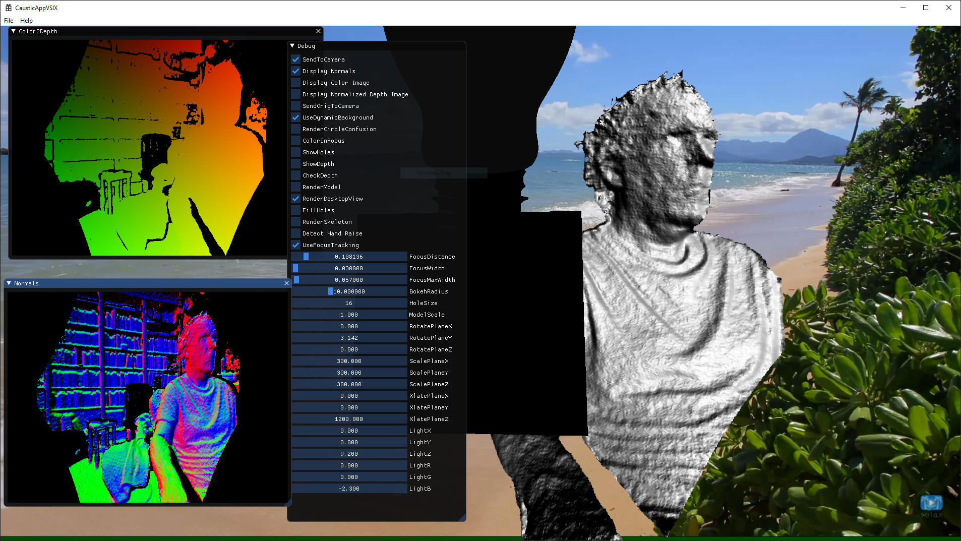
- Details
- Written by Super User
- Category: Uncategorised
- Hits: 12986
04/202/2021
I recently implemented marching cubes (MC) inside my Caustic renderer using compute shaders.
I started out with a pure CPU version, which is rather trivial to implement. See CMeshConstructor::MeshFromDensityFunction(). I then converted this CPU implementation into two different GPU implementations. The C++ side of these GPU versions are handled in CSceneMarchingCubesElem.cpp.
GPU Version #1
The first version is found in MCSinglePass.cs. The name of this file is a bit of a misnomer since my implementation actually calls this compute shader twice. The first time is only to retrieve the total number of vertices generated so that we can allocate a vertex buffer of the correct size. The second pass actually emits the vertices once we have allocated the vertex buffer. This version only outputs a vertex buffer (i.e. no index buffer), which means there is no vertex sharing.
GPU Version #2
This version enables vertex sharing by outputting both a vertex buffer and an index buffer. It is implemented as 3 separate compute shaders that are run as a pipeline with the following steps: MCCountVerts => MCAllocVerts => MCEmitVerts
- MCCountVerts.cs
This pass does two things. First it counts the total number of vertices that will be emitted by the final stage. Secondly, for each voxel it flags which vertices are referenced. Each voxel contains 8 values from the signed distance function (SDF) provided by the client. These SDF values indicate whether the voxel is considered to be inside or outside the surface. Since the SDF values are shared with neighboring voxels, each voxel only stores the SDF value for the 0th vertex (see Figure 1)
The other 7 values are read from neighboring voxels. From these 8 SDF values we have potentially 12 different vertices that intersect the surface. These vertices are located where the SDF value is 0. See Figure 2.
Again, since these vertices are shared with neighboring voxels, each voxel only emits vertices 0, 3, and 8 (assuming a polygon references them).
Updating of the total vertex count and setting a vertex's reference flag must use InterlockedAdd() and InterlockedOr() respectively. The reason is that multiple GPU threads may be attempting to update these values at the same time. The Interlocked...() calls ensure that the operation is atomic. The second key attribute that must be set is the globallycoherent modifier must be set on the variables we are calling Interlocked...() on. The reason for this is to ensure that writes to the variable are flushed across all GPU thread groups. - MCAllocVerts.cs
After the first stage runs we are able to allocate a vertex and index buffer of the correct size. This stage determines the index where each referenced vertex will reside in the vertex buffer. - MCEmitVerts.cs
This stage writes the actual data to the vertex and index buffers. Since we want to pass these output buffers as ID3D11Buffer to Draw() we can't declare them as RWStructuredBuffer. Thus we need to declare them as RWByteAddressBuffer.
Here is the final wireframe output

using the SDF function:
auto spherePDF = [](Vector3& v)->float
{
static Vector3 center(0.5f, 0.5f, 0.5f);
return (v - center).Length() - 0.5f;
};
- Details
- Written by Super User
- Category: Uncategorised
- Hits: 11505
21/09/2020
So, I'm building a demo for work in an app that is strictly Native C++. For the past decade whenever I've had to do UI work, I generally default to using WPF and C#. It's been quite a while since I built a UI front end using Native C++. I didn't want to have to interop between C# and C++, so I started to look for what the right way to do this is. The options are:
1) Win32 Native controls - Bit of a PITA and very old tech
2) WinUI 3.0. This is what Microsoft is pushing for the next UI incarnation for Native code (and managed code). Unfortunately, this is a bit of a mess and not complete.
Both of these solutions suck. So, I started looking at Open source solutions. The big two are wxWidgets and QT. I tried wxWidgets and its certainly better than using Win32 native controls. But, the programming model feels very antiquated (lots of macros). My former boss suggested looking at ImGui. Have to say, I love it. Simple to use and fast. Probably not great for a commercial app but for prototyping, it seems to fit the bill nicely.
Page 2 of 6